
Voltage drop is the reduction in electrical voltage as current travels through conductors. A common US electrical design guideline recommends keeping voltage drop around 3% on a branch circuit and 5% across the feeder and branch circuit combined.
These figures are commonly associated with informational guidance in the National Electrical Code (NEC). They are recommendations for general design, not universal mandatory limits. Actual requirements depend on the applicable code, equipment specifications and installation conditions.
Estimate voltage loss using our free AC/DC Voltage Drop Calculator .
Why Voltage Drop Matters
Every electrical conductor has resistance. When current flows, some of the supply voltage is lost along the conductors. Longer cable runs and greater current generally increase resistive voltage drop, while larger conductor areas reduce it.
Excessive voltage drop can prevent equipment from operating as intended. LED lighting may dim, electronic devices may reset and some motor loads may experience operational problems.
The percentage effect can be especially significant in low-voltage systems. A 1 V drop represents 8.33% of a 12 V supply but approximately 0.83% of a 120 V supply.
Voltage drop is only one part of electrical design. Conductor ampacity, overcurrent protection, equipment ratings, temperature and installation methods must also be evaluated.
Understanding the 3% and 5% Guidelines
The National Electrical Code is published by the National Fire Protection Association (NFPA). The current published edition is NFPA 70-2026, but jurisdictions may adopt different editions and amendments.
For general-use circuits, commonly cited NEC informational recommendations include:
- About 3%: a branch-circuit voltage-drop design target for the farthest outlet.
- About 5%: a combined voltage-drop design target for the feeder and branch circuit together.
The combined guideline does not mean an additional 5% beyond the branch-circuit drop.
Different combinations of feeder and branch-circuit voltage drop may be acceptable when they satisfy the requirements of the actual installation.
Some specialized applications have stricter requirements. Always check equipment specifications, applicable NEC provisions and local authority requirements.
How to Calculate Voltage Drop
For a simplified DC or two-wire resistive circuit, voltage drop can be estimated using:
Voltage drop = (2 × L × I × ρ) / A
Where:
- L: One-way conductor length in meters.
- I: Current in amperes.
- ρ: Conductor resistivity in Ω·mm²/m.
- A: Conductor cross-sectional area in mm².
For the simplified copper examples in this guide, resistivity is taken as approximately 0.0172 Ω·mm²/m at 20°C.
The factor of two accounts for the outgoing and return conductors in the assumed two-wire circuit.
Voltage drop (%) = Voltage drop / Source voltage × 100
Load voltage = Source voltage − Voltage drop
This simplified model does not account for all AC circuit conditions. Reactance, power factor, conductor temperature and load characteristics may affect actual results.
It should not be confused with a full conductor-sizing calculation using applicable NEC tables and design criteria.
Example 1: A 12 V DC Installation
Consider a 12 V DC device drawing a constant current of 5 A through a copper conductor with a one-way cable length of 10 m.
We will compare three conductor sizes:
- 2.5 mm²
- 4 mm²
- 6 mm²
For 2.5 mm² copper:
Voltage drop = (2 × 10 × 5 × 0.0172) / 2.5 = 0.688 V
This is approximately 5.73% of 12 V and leaves approximately 11.31 V at the load.
| Copper size | Drop (V) | Drop (%) | Load voltage |
|---|---|---|---|
| 2.5 mm² | 0.69 V | 5.73% | 11.31 V |
| 4 mm² | 0.43 V | 3.58% | 11.57 V |
| 6 mm² | 0.29 V | 2.39% | 11.71 V |
The 6 mm² example falls below a 3% comparison target under these assumptions. However, the NEC’s general branch-circuit recommendation should not be treated as a universal requirement for this DC device.
The correct conductor must also satisfy equipment voltage limits, ampacity, protection, temperature and installation requirements.
Example 2: A 230 V Circuit
Consider a simplified single-phase resistive AC example:
- Source voltage: 230 V
- Current: 16 A
- One-way distance: 30 m
- Copper conductor area: 2.5 mm²
- Assumed conductor temperature: 20°C
Voltage drop = (2 × 30 × 16 × 0.0172) / 2.5 ≈ 6.60 V
The estimated voltage-drop percentage is approximately 2.87%, leaving 223.40 V at the load.
This example demonstrates the formula only. It does not establish NEC compliance or conductor suitability. Actual conductor temperature and AC impedance may change the result.
What the Calculator Cannot Determine
An online voltage-drop calculator provides a planning estimate. It cannot approve a complete installation.
- Temperature: Copper resistance increases as conductors become warmer.
- AC impedance: Reactance and power factor can affect actual AC voltage drop.
- Startup current: Motors and other loads may draw more current during startup.
- Constant-power equipment: Some loads draw additional current when supply voltage decreases.
- Ampacity: A conductor with acceptable voltage drop may still be unsuitable for the current.
- Protection: Protective devices and installation methods must be assessed separately.
Practical Ways to Reduce Voltage Drop
Common ways to reduce resistive voltage drop include increasing conductor cross-sectional area, shortening cable runs, reducing current where practical and selecting an appropriate higher distribution voltage when equipment permits.
Cable length is particularly important because, with current and conductor area held constant, resistive voltage drop increases proportionally with one-way cable length.
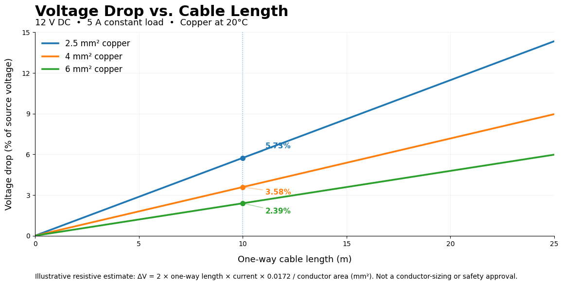
For example, doubling the cable length while keeping the same current, conductor material and area approximately doubles the resistive voltage drop in this simplified model.
For actual installations, changes must always be checked against equipment requirements and electrical safety rules.
Frequently Asked Questions
Is a 5% voltage drop always acceptable?
No. The commonly cited 5% combined recommendation is not universal permission for all installations. Sensitive loads and specialized equipment may require smaller losses.
Should I enter cable length one-way or round-trip?
For the NetOps calculator, enter the physical one-way cable distance. Its simplified DC and two-conductor calculations already account for the outgoing and return paths.
Does increasing conductor size always reduce voltage drop?
For the same material, temperature, length and current, increasing conductor area reduces resistive voltage drop. However, conductor selection must satisfy all applicable technical and safety requirements.
Technical References
- NFPA 70 — National Electrical Code
- Schneider Electric — Electrical Installation Guide: Maximum Voltage Drop Limit
- Copper Development Association — Recommended Practices for Installing Copper Building Wire
The 2026 NEC is the current published edition, but the edition adopted and enforced varies by jurisdiction. Always confirm applicable requirements.
Calculate Your Own Voltage Drop
Use the NetOps AC/DC Voltage Drop Calculator to compare conductor sizes, current, voltage and cable length.
Explore more technical calculators and generators in the NetOps Tools Directory .
Last reviewed: October 26, 2026
Developed and maintained by: NetOps Tools
Purpose: Educational information and
preliminary technical planning.